

Last month, Hank (K1DOS) came over and demonstrated how he could send and receive mail through an FM packet connect from his car using a computer and a little TNC. I agreed it was pretty cool, and he pointed out that I could do much the same the the PK232 gathering dust on a shelf in my shack. I had, in fact, forgotten that I had one, but this provided the impetus to try to set it up.
I received this unit a year or two ago from Bill Hook (W3QBC) at the NIH Amateur Radio Club. He said he didn’t have much use for packet any more and handed me the box and a pile of manuals and notes that documented how he had upgraded it module by module since the mid-eighties.
I was aware that packet had been popular before home internet became common, and I had seen videos of on-air BBSes being run over VHF links. Also, I knew that until fairly recently, people used packet for spotting DX. My only formal connection with packet, though, was using APRS for position reporting. My VX-8GR handheld has an integrated GPS and on SOTA activations, I’ve brought it along to squirt status and position updates so AI4SV-9 could be tracked on sites like aprs.fi or findu.com.
The PK232 is a fantastically successful product thanks to the excellent engineering that went into it. The design was so open-ended that the 1980s device was expandable over a decade and half of upgrades and is still useful today. Despite that, these boxes are commonly seen at hamfests for a few dollars. In many ways, digital sound card modes displaced these hardware solutions, but there are still some things this box can do that a sound card cannot:
- Pactor – This is a proprietary mode. The PK232 can only handle pactor level one which is darn slow, but this is good enough to use the Winlink system to send and receive email over HF;
- It can serve as an interface to operate rigs in FSK mode, which may produce more accurate tones than a sound card. Also, operating in FSK mode on my TS-450 makes available the narrow CW filters that I have installed;
- With the PK232 doing the heavy lifting, there are minimal demands on the host system. In fact, all you really need is a dumb terminal and knowledge of a few commands from the PK232 manual, which is online as a pdf. It is pretty amazing that the heart of the PK232 is a Z80 chip, the same CPU found in the TRS-80 model I.
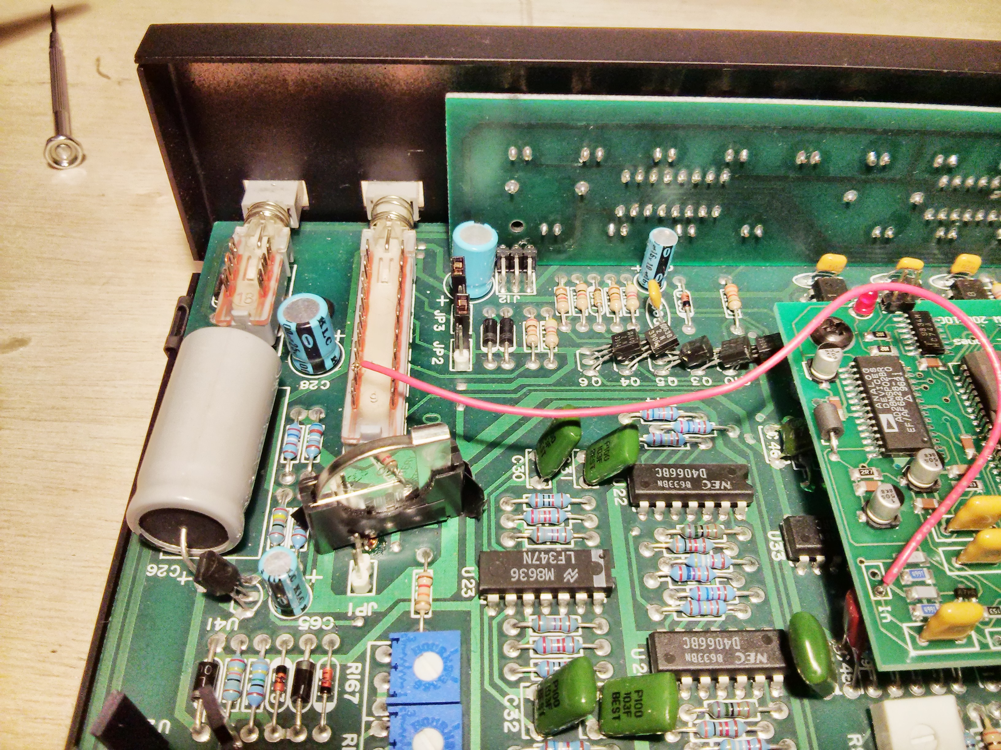
I received the PK232 without any cables, so my first step was to make a power cable with a 2.5mm barrel connector at one end and power pole connectors at the other. I was relieved to see that LEDs came on when I plugged it in. Reading through the manual, the LED pattern suggested that the PK232 had remembered some previous settings, which suggested that an internal CR02032 3V lithium battery was still powered. I wanted to reset the unit, so I opened it up and was going to pull the jumper that allows it to reset. When I got in there, though, I saw that the lithium battery looked fairly corroded. I tried to yank it, but it was soldered in very securely. I measured the voltage across the battery as 2.1V — still enough to retain memory, but perhaps not reliable for long. My only option for removing the battery was to clip its holder near the base, which I did. I found that I could then replace the holder with one from my parts bin by soldering it to the stubs of the original clip. This left me with a battery holder at a strange angle, but it means that I can replace the battery with ease in the future (should this unit survive a few more decades).
Getting LEDs to glow is always a good sign, but to know if anyone was actually home in the PK232, I needed to get it talking to a computer.

The PK232 was designed to connect via RS-232 serial cable to a computer or terminal. The manual provides a long list of text commands to put the PK232 into various operating states. At this point, I didn’t have any of the original software for the PK232, so my only option was to type these commands directly. It took me a while to dive deep enough into the junk pile to find a bona fide RS232 cable plus the various adapters needed to take it from a 25pin male connector on the PK232 to the 9-pin male connector on my toughbook laptop. Luckily, I did have a computer with a real serial port and didn’t have to deal with the additional variable of getting a USB-serial converter to play nicely with the PK232.
The PK232 came up in its default (and strange) serial configuration of 1200 baud, 7 data, even parity. Using Windows hyperterminal, I sent the device a “RESET” command and then changed the terminal parameters to a more reasonable 9600 baud, 8 bit, 1 stop, no parity. I then sent an asterisk so the PK232 autobaud detect could synchronize. This worked, and left me at the “cmd:” prompt sent by the PK232.
The PK232 has a switch on the front that allows selection of two radios, and there are ports on the back that correspond to these radios. These ports are bare pins with 0.1 inch spacing, like the headers on an Arduino board. Each radio gets five pins: ground, sound in, sound out, squelch and PTT. Additionally, there is a 3.5mm audio input jack for each radio.
Before messing around with the 5-pin headers, I used the 3.5mm jacks to test the receive function of the PK232. I took sound out from the TS-450, set the PK232 to RTTY (Baudot mode, 45 baud, 170 Hz spacing) and found some strong RTTY signals. It took just a bit of fiddling with tuning to get the signal centered according to the PK232 signal display and to get the sound output/PK232 input sensitivity in the right range, but once I did, the PK232 did an excellent job of decoding the signal and rejecting random noise between signals.
Now that I was convinced that the PK232 wasn’t brain dead, I set up a loop back test by routing the Radio number one “audio out” to the “audio in”. I set the mode to VHF and packet and was able to “CONNECT” to myself and to echo text in “CONVERSE” mode. This assured me that a number of circuits were intact, at least for packet, so I went ahead and built a cable for my Yaesu FT-817nd. Ben (NN9S) had donated a CT39A data cable for the Yaesu, so my biggest issue was how to physically connect the wires to the pins at the back of the PK232. I soldered a 5-pin row of female SIP headers to a small piece of vector board and wired it up. Maybe not the most robust connector, but adequate for my purposes. For a little strain relief, I added a dab of hot glue where the cable comes in.

Testing that packet works must have been much easier in the past: the manual recommends tuning around on “common packet frequencies” until other stations are heard, and then attempting to connect to one. I listened for quite a while and didn’t hear anything on these frequencies. A little internet search shows that there are some packet networks in my area (e.g., the Virginia Digital Network) but I didn’t hear anything on the radio. It occured to me, though, that there is one reliable, high activity service that regularly sends AX.25 packets: the APRS system. I tuned to the US national frequency of 144.390 and heard bursts every few seconds. Reassuringly, the PK232 decoded the APRS messages, although it took me a bit of reading through a very helpful primer and the original specification to make heads or tails out of the short messages. I left the radio on overnight so the PK232 could build a list of which stations were heard, and particularly, which station were heard directly, i.e., without digipeating.
Listening is great, but I was eager to start transmitting. I figured that I could test out my set up using APRS. I could hear two large “backbone” stations directly, one in Tyson’s Corner Virginia (NV4FM-5) and the other in Southern Maryland (KV3B-1). There were also some smaller home stations in Virginia, but I figured that it would be best to start with the larger stations. I only have 5W output, but both stations should be in the “beam” of my 2m antenna, a 5-element antenna that was originally built for satellite work,but which is now on a tripod jammed between the rafters of the attic.
There was an immediately problem, however. When my rig should have been transmitting, nothing happened. The indicators on the PK232 lit up correctly, so I knew that it thought it was transmitting, but the radio was inert. I double-checked that the wiring was correct. By grounding the PTT line at the PK232, I was able to trigger the radio’s transmit, so the problem appeared to be in the signaling between the PK232’s microprocessor and the PTT line.
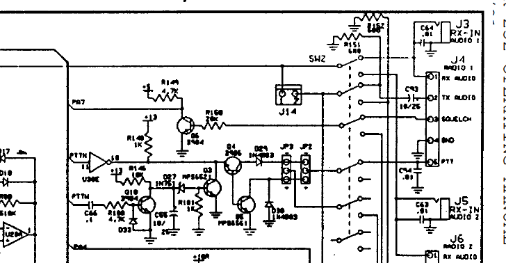 Whatever was going on, it was clear that the transistor responsible for taking the PTT line low (Q5) was not doing its job. I did a quick internet search to see if anyone else had run into the same problem and there was a report of a similar failure that was fixed by replacing Q5 (an MPS 6561 NPN) with a 2n2222. I pulled Q5 and tested it — it was bad. However, replacing it didn’t fix the problem. I traced the signal forward from the microprocessor to a 7406 inverter chip (U38). The PTTW signal into the chip was working correctly (pin 11), but the output of that particular inverter (pin 10) was always low, whereas it should have been the opposite of pin 11. I wasn’t sure if the chip was dead or if something downstream had effectively shorted to ground, pulling the pin low regardless of how it was driven. I thought that some of the downstream transistors and/or diodes were likely components, so I worked through the transistors, testing them one at a time.
I don’t know what happened to this unit, but something blew a number of these transistors — I suspect that PK232 might have been been zapped either due to an electrical storm, or perhaps by being connected to some high voltage tube gear with negative keying. In any event, I made my best guess at replacing the bipolar transistors with what I had on hand. Next I tested Q3; it showed no voltage on any leads, keyed or not. It was an MPS 6521 and also tested bad. The 6521 is an NPN transistor with higher gain, so I replaced it with a 2n4401. Q4? Yup. Also bad. It was a 2n3906 — at last, something that I actually had in my parts inventory. I replaced it with the same. At least Q10, a 2N3904 was not blown. I was beginning to wonder if my meter was flaky, but all the measurements were repeatable. In yanking the various transistors, I was able to test the diodes in place (29, 30, 33), and they looked good. The inverter chip itself, however, still looked dead on pin 10. I chopped out the IC, cleaned up the pad and stuck in a new 74LS06. Now, it worked correctly, with pin 10 moving high/low in opposition to the state of pin 11. Everything downstream also checked out and the PTT line now correctly triggered the radio.
I squirted a test APRS message to NV4FM-5: I set the unproto path to “TEST VIA NV4FM-5” and squirted an empty message, just hitting the carriage return in converse mode. I was lucky that it was picked up. Next, I set unproto to “AP817X VIA NV4FM, WIDE1-2” and sent a location message. I saw the message forwarded and was able to find it on aprs.fi. I set the repeat time to 30 minutes and noticed that not every packet was making the relay — either due to collision or perhaps marginal power since I was QRP. I had similar mileage with KV3B. I think the problem is more likely due to collisions with signals that I can’t hear, but that these centrally located stations with large antennas can hear. That, plus FM-capture effect, may mean that I need a more powerful radio to inject messages with higher confidence. I may also need to understand APRS and the local landscape better to optimize my messaging.

Next, I wanted to replicate Hank’s trick of sending mail via packet. He had helped me out by installing RMS Express and Paclink when he visited, so at least I didn’t have to worry about that. I looked at a map of packet nodes and saw that there were some in the region, but perhaps not close enough to work with 5W. I tuned the rig in packet mode to their frequencies and set my HT to the same frequency as a monitor. I heard by packets go out, but never got a response. Knowing that the PK232 sends and receives packets correctly, I have to assume the problem is just reaching the RMS node with my signal. To confirm, I brought the same computer out to my car, plugged into the car’s serial cable and used the Kenwood B2000’s built-in AX.25 TNC to confirm that with more power (and higher elevation — the roof of the local metro station parking lot), I could reach these machines.
So, short of building an amplifier (a project on my list) or getting a more powerful 2M rig (not currently on the list), I’m not going to be able to work the VHF RMS nodes from the house. However, I did manage to send email using the FT817nd by using the EMAIL gateway for APRS. By setting the destination to “EMAIL” and sending a correctly formatted message, a short text string can be sent to any email address. I haven’t tried it yet, but there is also a APRS-Winlink gateway. I’m less keen on this approach because it would take multiple APRS squirts to send a single message. APRS is really meant for short messages related to local, real-time tactical information, so tying it up with email doesn’t seem like a good policy.
I created another cable for radio two, my Kenwood TS-450. The PK232 manual provides wiring diagrams for quite a few rigs including the TS-450. I could have gone into the mic jack, but felt it was preferable to use the ACC2 port, which provides output sound independent of front panel AF gain setting. The PK232 documentation and some experience reflected on the internet indicate that the TS-450 is susceptible to RF on the ACC2 port, so rather than use sound input, the common advice is to drive the TS-450 through the FSK line. This also makes the TS-450 narrow filters available in FSK mode.
The ACC2 port is a thirteen pin port, but the only lines that are brought over from the PK232’s radio 2 port are PTT, ground, and radio sound out. There is 5-pin DIN connector on the PK232 which provides a ground, FSK and R-FSK control lines. It also provides output for mark and space tones that are meant to drive an XY oscilloscope for RTTY tuning. Unfortunately, I didn’t have any connector that would fit this DIN, so I rerouted these lines to the header for an external modem. I don’t think I’ll ever add an external modem — if I had one, it would probably replace the entire PK232 unit. I made an adapter and brought these lines out to a small box with RCA phono plugs for these functions. At some point, I may add an oscilloscope (because it looks cool), so perhaps the mark/space lines will get used. I wired a female phono plug into the ACC line, so I could use a phono cord patch between the breakout box and the ACC2 port.
I confirmed that I could send and receive RTTY using the terminal. To operate in pactor mode, however, I had to alter the TS-450’s mark/space width from 170Hz to 200Hz. This can be done by holding down the “M.IN” button while turning the unit on, and adjusting menu setting 37 using the multi-knob. The radio retains this setting through power cycles.
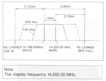
 The Winlink site has a real-time map of HF stations on the air. The map lists their call signs, center frequencies and capabilities in terms of pactor level. Using that map plus knowing propagation conditions, I was able to pick out some stations likely to be within range. With the radio set up in FSK-R mode, the dial shows the mark frequency, which should be 200 Hz above the space frequency. Therefore, I set the dial frequency 100 Hz above the channel center frequency indicated in RMS express. I had an outgoing email queued up, so I could confirm that this worked by looking at my gmail account afterwards.
I set power to 50W and adjusted my carrier level just below the point that ALC would kick in. After listening to make sure there was no activity, I clicked on “connect” within RMSexpress. The radio sent a few phasing bursts, followed by reply tones as the two stations synched up. The RMSExpress screen indicated progress of the session, and the email was spooled out. A few seconds later, the email was in my gmail account, sent over HF from here to a station near Norfolk, VA. Not a globe spanning connection, but proof of principle. It was early morning, so this was an 80M connection. I’ll have to try it again later in the day on the higher bands.

Thanks for posting PK-232 reborn article, it’s well written and very informative. I also have one that am considering for monitoring APRS.
If ever need EPROM code, this site has:
http://www.repeater-builder.com/aea/aea-index.html
Thanks. Good to know the code is out there 🙂 73 – Jack
Hi Jack
One terminal SW maybe interests you.
I used a DOS version terminal sw in 1980 tales for amtor and pactor.
Like you I become interested in vintage stuff.
I recently searched my old PK232MBX onto my ham desk out from my junk shelf close the place where a lot of birch wood is piled to wait for cold winter and a couple of wine glasses in front of live fire burning in fire place.
Wiped most dust away and started to investigate how to connect it to my Icom IC7300.
It was evidently impossible to install old DOS terminal SW to Windows 7
So something else should be done.
The old DOS sw had a name Lan-link .
I Googled and Heureka Heureka
I found.
http://therightrequirement.com/
There it was in blue text: LanLink
I found a modern version capable for Bill-boys Windows 7.
LanLink is easy to use.
It is very sofisticated program written by professor Joe Kasser G3ZCZ
I think it not very widely used but anyhow worth trying with PK232.
I am optimistic to make some Pactor 1 chatting with this Hw and Sw combination on 14MHz.
If ARQ trafic (exept very expencive Pactor III) is no more having users I am anyhow satified to use it for Baudot, CW, Packet, Signal, ect. in parallel with usual digi modes
Active problem now is how to increase PK232MBX audio output level.
It is low microphone level.
I don’t want to swap audio to rig microfone input and mic back again but parallel in with PC audio line output to rig more or less sensitive line input.
This maybe needs some soldering.
Jack
It was nice to read your essay in your blog
HNY 2019 and 73
Risto OH2BT